I just finished rewiring my studio with custom Mogami DB25 snakes and a TT patchbay. I couldn’t find much information on the web while I was doing this, so hopefully this helps someone out. (Open any of these images in a new tab to see them larger.)
A quick note before I go on, you should only attempt this if you are very comfortable with making cables. This is an advanced project and you should have a lot of 1/4″ and XLR cable construction under your belt before attempting a job as big as this.
Why Do This?
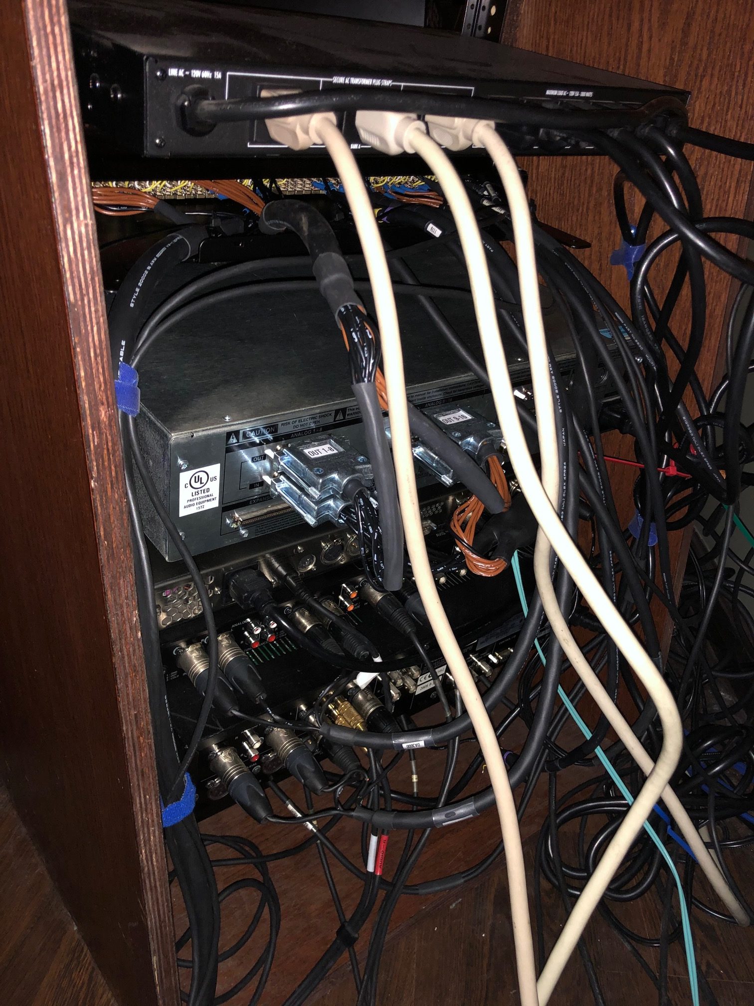
For years I’ve been using three TRS patchbays and a mountain of DB25-TRS snakes, most of which I got for free. This was problematic for many reasons. First, the cabling was both poor-quality and too long for my needs. I wasn’t getting the audio quality I would get with shorter, high-quality cables. And there was so much cabling back there that around 25% was abandoned and hopelessly tangled.
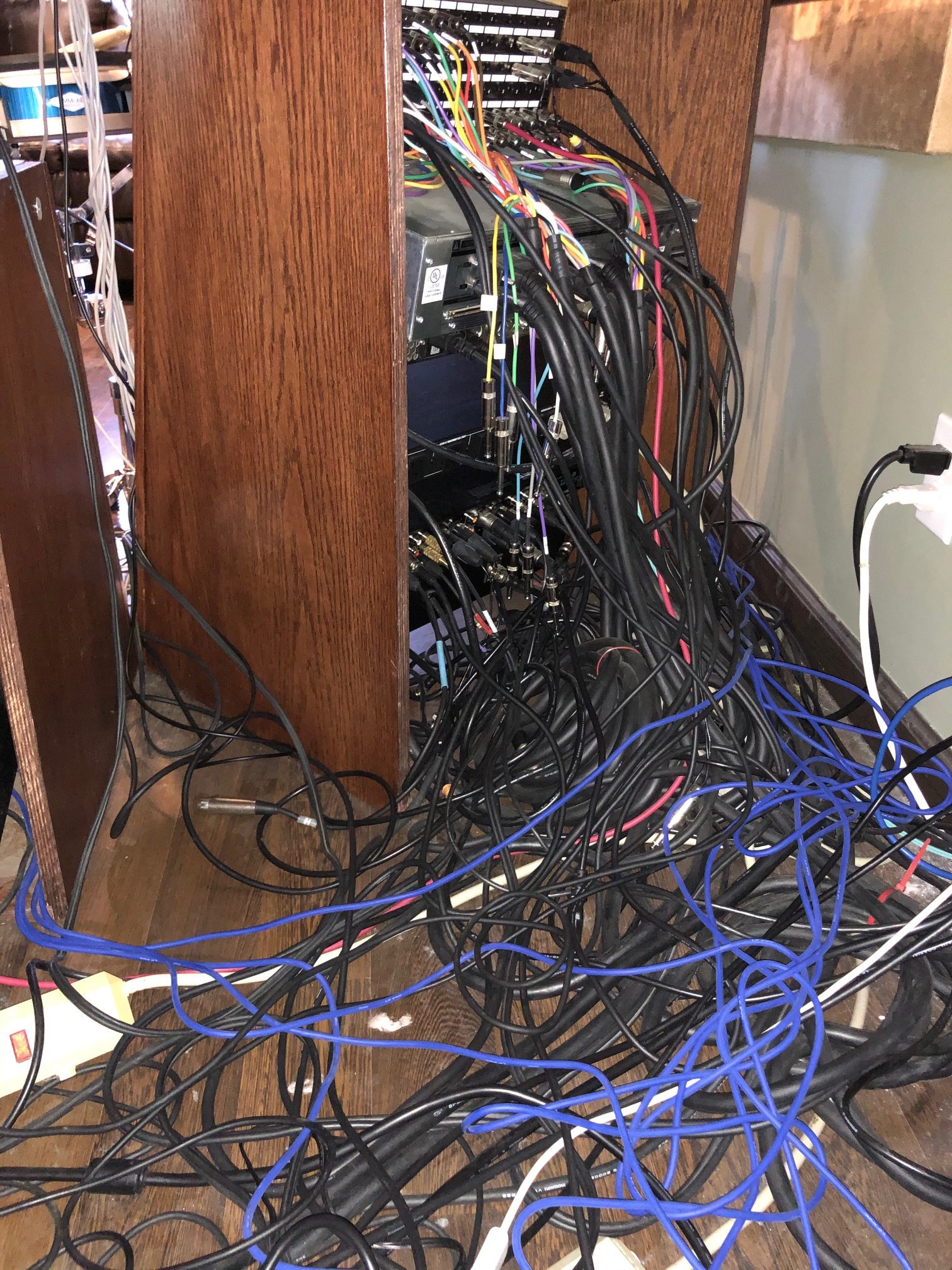
Another issue with TRS patchbays is that the cables on the back come loose. My rack is at a slight angle, and cables would somehow work their way out behind the rack. Finally, there were two more connectors between the source and destination. Every connector or adapter degrades the signal, so I wasn’t getting the best quality I could.
I initially thought about buying shorter Mogami pre-made snakes. But their Mogami Gold DB25-TRS snakes were $230 each, and I would need at least five of those. Plus I would still have the problems in the second paragraph. I could have gone with a patchbay that uses DB25 connectors on the back instead of soldering everything myself. But that still has the second paragraph issues and is almost as expensive as buying a bunch of TRS snakes.
I found a website called Mister Patchbay.com. He sells refurbished solder patchbays for around $150. So that’s the route I went, and I would figure out how to make the cables that I needed. The connectors would be soldered directly to the bay for the best quality, so this was both the cheapest and best option for me. I had great luck with the bay I bought from Mister Patchbay. Note that at the time of this writing, it appears that a link squatter grabbed his site with the big blue bars, but that’s actually his site design.
Another question you might have is, why use a patchbay at all? Beside the the flexibility of changing signal routing in the studio, it’s just a practical way to go. Pro interfaces use DB25 balanced connectors, so to connect a synth to that I would need to make a special DB25 with one very long cable, one short cable, etc. Then if I changed something I would need to make a new cable instead.
DB25 Cabling
I happened to have a lot of Mogami cabling in my garage from previous studio setups, going all the way back to ADAT studios. I had a bunch of Mogami 2934, which is 16-pair cabling. Ideally you should use 8-pair cabling to make DB25 cables, but this is what I had so I would make it work.
Before we move on, let’s talk about the right tools for the job. I have made a bunch of cables with Mogami multi-channel snakes like this, but it was always a struggle to strip the tiny inside cables. It turns out that this is 26-gauge wire and the smallest setting on my wire stripper was 20 gauge. Once I bought the right tool, stripping these was easy. My point here is that if you are going to be stripping and soldering a LOT of wires, have the proper tools to make this as easy as possible.
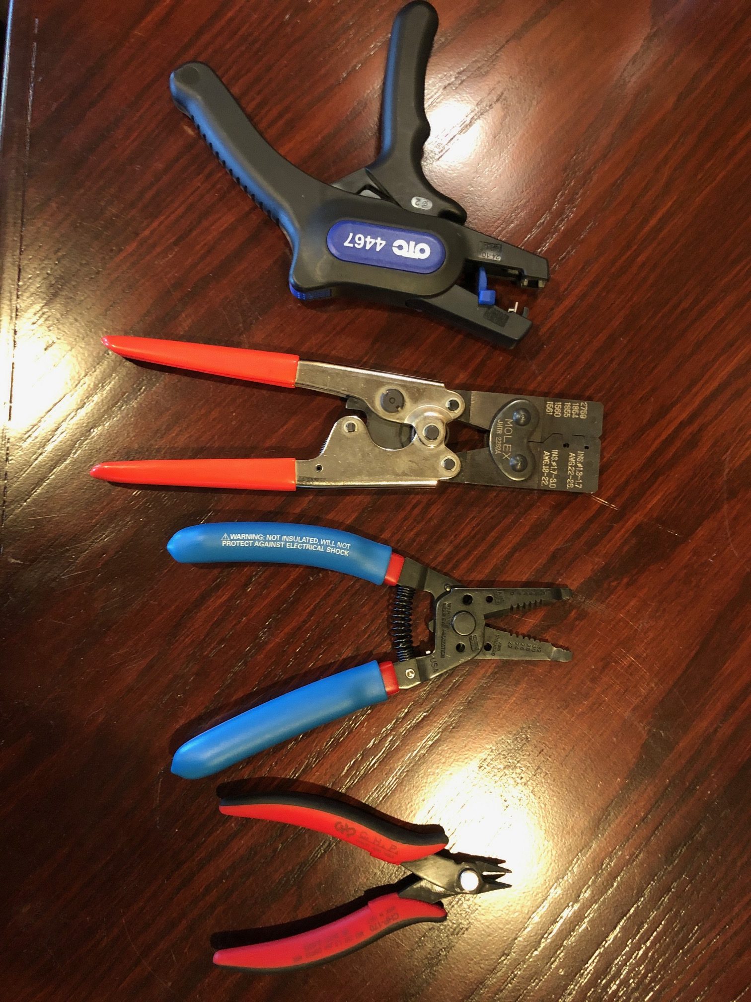
I use an OTC 4467 to strip the outer jacket off the cable. It is fast and easy and doesn’t cut much of the wire shield. Once that was off I used the new Klein stripper for the inside wires.
For the parts I needed to make DB25 cables, I went to Redco. I ended up making six DB25 male connectors and here’s what I used:
- Pan Pacific DH-25HP D-Sub 25 Pin MALE Crimp Style Connector
- Pan Pacific DH-PIN/M-MCH Macined MALE Dsub Crimp Pins-100pc
- Redco DB25HM-4/40
- Dsub Pin Insertion and Extraction Tool
The gear I was connecting (SSL Alphalink AX and SPL 2489) are both made in Europe but use 4/40 threading for the connectors, so it looks like that’s the standard.
Next, I added crimp pins to my cables using a Molex JHTR2262A. Place the crimp pin in the crimper with the pin facing the back of the tool. Close it just enough to hold the pin in place, and hold it from falling out with your right index finger. Feed the wire into the hole of the pin on the front of the tool. Then squeeze until it clicks and let go. I didn’t tin (solder) the leads before putting them in the crimp tool, and I didn’t solder them after crimping.
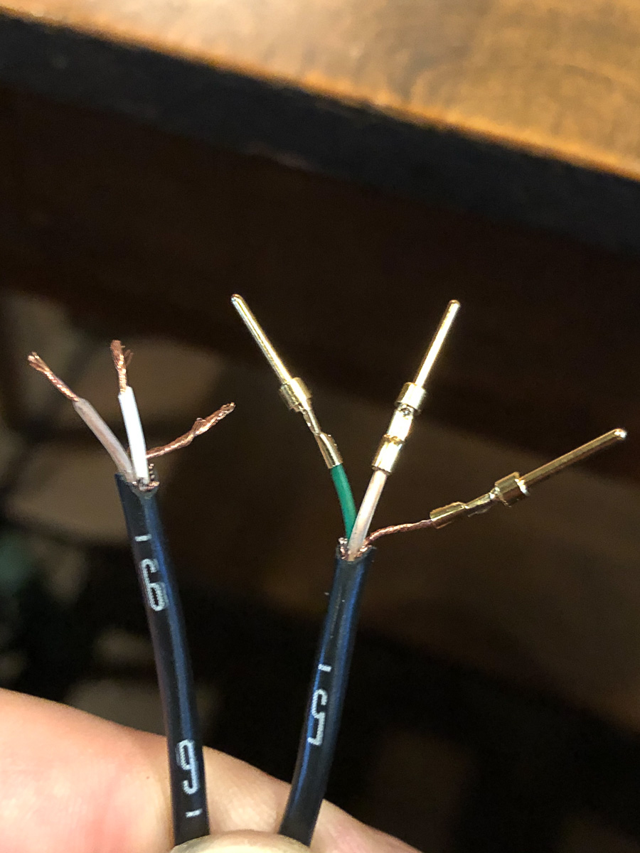
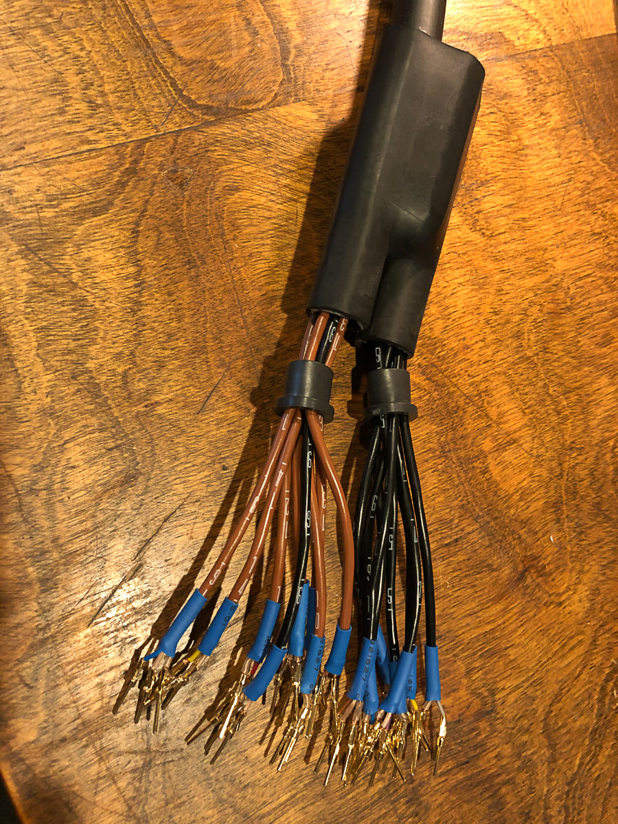
Next, shrinkwrap everything. I put a small shrinkwrap jacket on the ground wire, and I added shrinkwrap to the base of each cable where it was stripped. This is to prevent wires from touching and shorting each other, including half the shield you trimmed off so it will fit in the pin.
If you’re using the DB25 hood I mentioned above, or one that has a rubber protector for the cables, put that on now. Then use the DB25 tool to stick the pins into the DB25 block. I had such little room on my wiring that I had to get all three in the holes before clicking them all into place. If you need to pull a pin back out, put the pin back inside and rotate it around the crimp pin while puching from the other side until it releases.
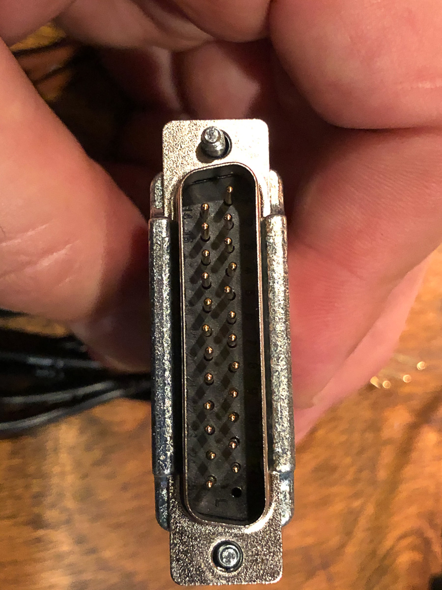
Use the TASCAM DB25 wiring standard [PDF file] for most gear (I think older Avid and Yamaha gear might be different but this pinout is now an AES standard.) The pinout on this page matches what you see from the back, so skip the first hole then go ground-cold-hot from channel 1 to 8. (Sidenote, in the early ’90s this pinout was once proprietary and not published by TASCAM so you would have to buy their cabling.)
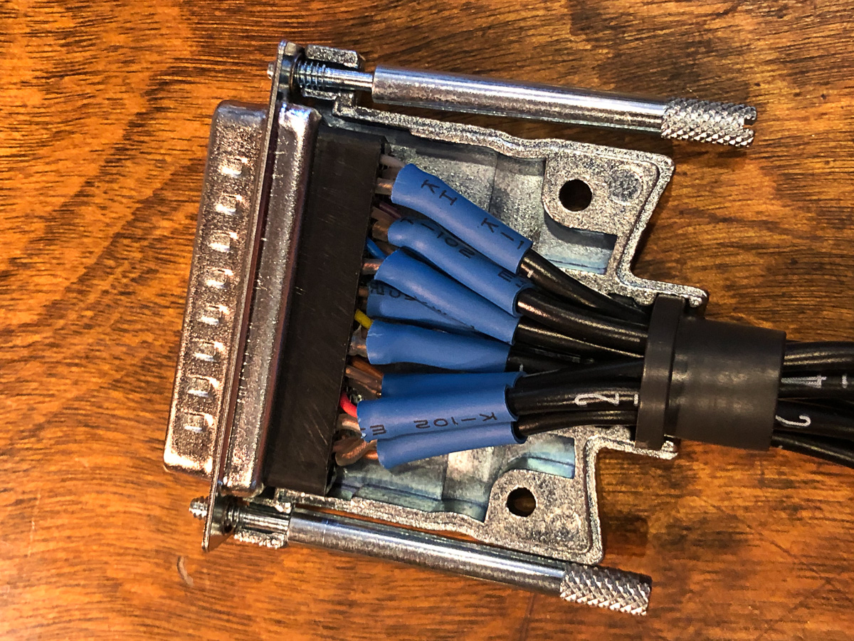
Place the DB25 in the hood, put the thumbscrews in, and attach the top. I repeated this six times and I was finished with one end of the cable.
Wiring the Patchbay
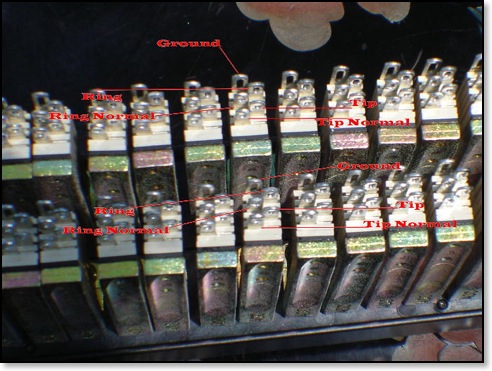
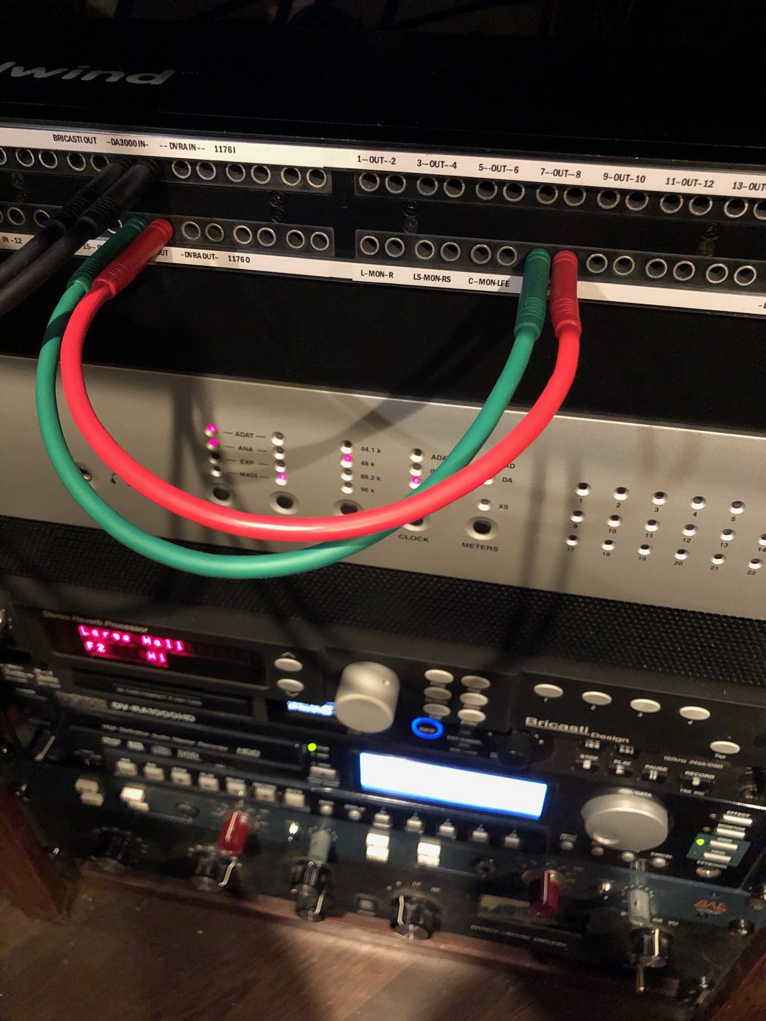
This is the pinout for the solder patchbay I was using. It’s a Whirlwind patchbay, but was made by ADC for them. The first step for me was normalling the patchbay, so that the top row would connect to the bottom row by default without needing a cable. I half-normalled the connections from my synths to the converter inputs, which means the top still goes to the bottom if I plug into the top, but it no longer does if I plug into the bottom.
There are dozens of articles online describing what normalling is, but I couldn’t find one that told me how to actually do it. Here is how it works:
- Connect your source to the Tip-Ring-Ground on the top row (Hot-Reverse-Ground, whatever you call it.)
- Connect a wire from the Tip of the top row to the Tip-Normal on the bottom row
- Connect another wire from the Ring on the top row to the Ring-Normal on the bottom row
The way I did it was to cut and install the wires first, but only solder them on the bottom. Then when I connected my synths and other sources, I put the hot signal next to the hot-normal wire and soldered them both.


One tip for making less of a mess on the back of the patchbay is to cut the center channels shorter than the outside channels. In my case, the cables for channels 1 and 16 of the snake were 1 unch longer than the cables for channels 8 and 9.
Again I added heatshrink to the ground wire and more around the area it was cut to avoid cables shorting out. You can see in the images where I haven’t heated them up yet that there is a bit of shield spilling out.
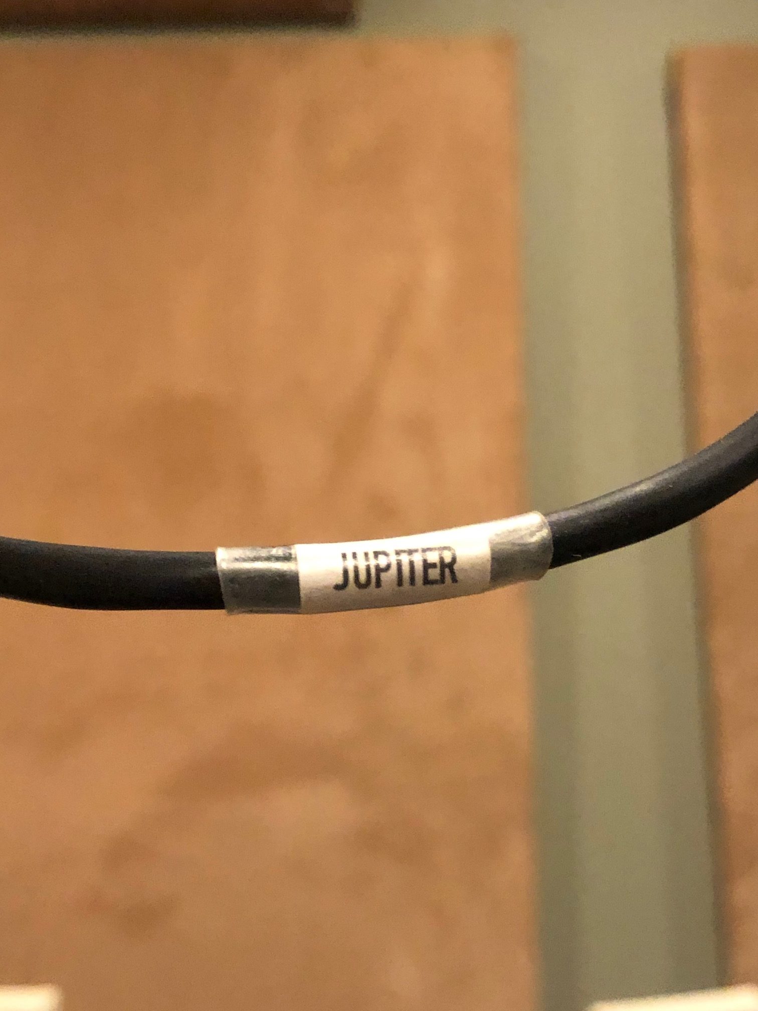
In most cases I made new or reused Mogami cables and snakes for the synths and effects. I also used some Gepco AES cable because I had that left over from another project. Before making the cable it’s useful to heatshrink a label to each end. Print the label and shrink it to the cable using clear shrink tubing. Another cable tip I’ve picked up is to tin all the leads then cut the ground a bit shorter. This gives you a bit more strain relief on the cable because that’s the strongest wire (wrapped around the rest.)
It took me a few tries to get the labels looking OK. If you’re using the same ADC patchbay I did, here are the labels I made (Excel doc.)
The after photo is not going to win any awards but it’s much more efficient and tidy. And out of the 400-ish connections I soldered only 3 needed help, which isn’t bad. I tried to run the audio cables on the left and power on the right side to avoid noise where possible.
I hope this is helpful to someone. If you have any questions, or if this writeup helped you, please leave a comment below.
[Edit, April 2021] After four months this is still working great but I wanted to add a few notes:
- Be sure to leave enough slack in your cabling to have a “service loop.” This allows you to pull the patchbay out to change or add things without disconnecting everything first. You might want an addtional ~12″ of cabling for this. (But the cost adds up if you’re using expensive cabling…)
- This patchbay is a “floating ground” design. The ground connector doesn’t connect between the source and destination in the normals. This keeps things quiet and works for almost everything, but I found a few synths wanted to have the ground connected. You can test this by hooking everything up and then using a patch cable to connect the source to the destination. If there was a hum before, and the hum went away when you patched (because the ground is now attached), then solder an additional wire between the ground on top and bottom.
Aaron
December 10, 2020 at 4:06 pm
Quite the project, Jeff!
I just tried soldering for the first time with some DIY eurorack. This looks like days and days of work.
Hope you are enjoying your new studio setup.
Leo
October 14, 2021 at 8:36 pm
Exelent work!! congratulations.. I hope to build something like that one day.. THAANKS FOR ALL !!!